Configure Data AcQuisition (DAQ)
A DAQ configuration defines the device used for generating signals and reading measurement data. ACME provides an API abstraction layer around a DAQ, and is able to work with different API's to read/write signal data. The easiest way to read signal data in ACME is by using an audio interface.
Managing DAQ configurations
On the Measure tab, create a new device configuration by right clicking on
the dropdown box in DAQ configuration:
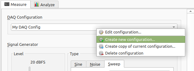
Here you can choose to:
- Edit the current configuration (if any)
- Create a new configuration
- Create a new configuration by copying the currently selected configuration
- Delete a configuration
DAQ configuration presets are stored on your computer right after creation and will be visible every time you restart ACME.
Editing a configuration
Global settings
When you edit an existing configuration, or create a new one, a dialog will open:
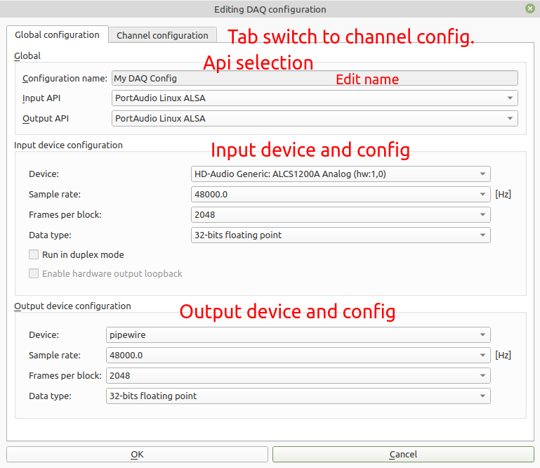
The DAQ configuration has two tabs. The first is the global configuration. The settings apply to both input and output settings. You can control input and output independently, but the configurations stores settings for both input and output simultaneously. ACME allows the usage of only one input and one output device at the same time.
- The
Configuration nameis a free text field where you can enter the name of the configuration. Duplicate names are not allowed. - The Input API / Output API show the currently selected API for the input and output.
- When a device supports duplex mode, the input and output can be coupled to
the same device. In that case, the
Outpput device configurationis greyed out, and theInput device configuration settingsapply to both input and output. - For the
Input device configurationthe sample rate can be set, this is the amount of samples that are taken per second (for each value). Lower values allow for smaller measurement file size, but also limit the highest maximum frequency that can be analyzed. - The
Frames per blocksetting is advanced, and determines the real time latency in the real time viewer. Too low values might result in buffer X-runs. Advised is to leave this value to the default of 8192. Data typeis the format for which samples obtained from the device. The allowed settings here are dependent on the device and the device driver. Floating point values are the most precise, but sometimes they are already converted from fixed point. This depends on the underlying device. It is advised to use either 32 bits fixed point of floating point.- The
Run in duplex modecheckbox switches the device to duplex mode. This lets the input and output stream run on the same pace. This is not supported by all devices. - For some devices, such as the DT9837A, a hardware loopback exists. In that case this button is enabled and an artificial input channel appears, that copies over the output signal generated with the Signal generator.
tip
If you have detailed information of the sample resolution of the used device / sound card, you can set the value of the data type accordingly. ACME stores the raw data in that sample format. For example, if the device has 16 bit resolution, the resulting measurement files will be half that of the case of 32-bits.
Channel settings
The second tab contains settings for each channel. Depending on the selected API / device combination, some settings might be grayed out.
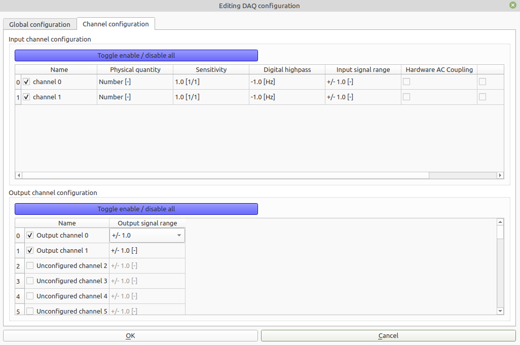
Depending on the selected input / output device, the available input and output channels is listed. From the given channels of a device, a subset can be enabled for input. These have to be checked next to the name.
- The checkbox next to the
Namefield toggles enabling this channel. Any channel not enabled is not visible in thePPM,Real time viewernor taken into account in a measurement. - The
Namefield allows for a unique name for each channel. Duplicate names are not allowed. - The
Sensitivityfield allows for setting the sensitivity. See background info below. Physical Quantityis the kind of signal that is measured ultimately and depends on the attached sensor. For a microphone, this is acoustic pressure. Changing this setting is useful e.g. for measuring sound pressure levels, and sets the proper reference levels when postprocessing.- A
Digital highpassapplies a first order digital highpass filter to the incoming data, before storing. This can be used to remove unwanted DC offset from the measured signal. When the frequency value is <=0, the digital highpass is turned off. Otherwise, it determines the cut-on frequency of the used digital highpass filter. Hardware AC couplingis another option to remove unwanted DC offset from the measured signals. If the device supports it, checking this box will enable a hardware AC coupling. This can be done, for example, by placing a capacitor in series before the ADC. The combination ofDigital highpassandHardware AC couplingis possibly, but superfluous.IEPEis a sensor power supply. This can be turned on for some sensors, for example measurement microphones and accelerometers.
warning
Turning on IEPE lets the device put a bias voltage of (> 10 V) on the channel. If your channel configuration is incorrect, it might harm the incorrectly connected device.
Sensitivity settings
The sensitivity has a unit of , where is the unit of the physical quantity and the unit of the data provided by the DAQ. For example when measuring acoustic pressure with an audio interface, the sensitivity has unit Pa. When in this example DAQ provides calibrated voltage data, the sensitivity has unit V/Pa. The following equation is applied to scale the raw data:
where is the physical measured quantity for channel and is the sensitivity for this channel. When data is stored as floating point, this equation is directly applied in this form.
Fixed point data caveats
Fixed point data is interpreted as fraction of full scale. So for fixed point data, the value is computed as
where is the maximum positive value that can be stored for the integer data. For example, for 16-bit integers this value is , for 32-bits integers this is .
When fixed point data is shown, it is always scaled to this maximum value, representing a number between -1 and 1.