Hardware
This section covers the hardware setup of µZ, including cabling.
Tube
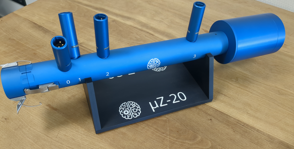
Place the main tube on the base and mount the end cap, as shown above. Remember to mount the appropriate end cap for the desired measurement configuration:
- without tip microphone for 4 microphone mode
- with tip microphone for 5 microphone mode
All part are connected using a twist and latch system. An example of the procedure for mounting a part B onto another part A is as follows:
- Position part B such that its two grooves line up with those on part A. On sample holder parts only look at the grooves that extend towards the part it's being connected to.
- Slide part B onto part A.
- Twist part B in a clockwise direction until only one of the grooves on parts A and B line up.
- Tighten the connection by closing the latches
The video below shows the procedure. Here part B is the end cap and part A is the main tube. The procedure is the same for all connecting parts.
Parts can be disconnect by following the mounting procedure in reverse.
warning
When closing and opening the latches, guide them with your fingers and prevent them from snapping with a loud click. Pinch the handle between thumb and index finger and slowly move it to its position, as shown in the video above. The snap releases enough energy to damage the surface finish of the aluminum parts. Furthermore, it sends a mechanical shock through the microphones, which can cause a change in their response. Repetitive snaps might cause permanent damage.
The main tube, calibration tube and sample holders contain O-rings to ensure airtight seals between the parts when the system is assembled. It is possible that repeatedly removing and mounting parts can cause the O-rings to fall out of their grooves. When doing measurements, periodically check whether the O-rings are still in place, especially when the results are not as expected. Spare O-rings are included with the system to replace ones that might get lost during use. If additional parts are needed, please contact us.
Cabling
Audient EVO 16
warning
The Audient EVO 16 audio interface is configured to apply power to the microphone inputs immediately on start-up. It is recommended to connect all the cables before turning on the EVO 16.
µZ comes with an Audient EVO 16 audio interface. The device can be turned on by connecting it to power using the power cable. Connect it to the computer running ACME via the USB-C cable. Depending on your operating system, additional drivers might be required to fully use the EVO 16's capabilities. For more information, check the Audio driver requirements section.
All cables are connected on the rear panel of the EVO 16. An overview of which cables are connected to which ports is shown in the picture below. Each connection will be discussed in more detail in the following.

note
The Audient EVO 16 audio interface has 8 line outputs. However, it is important that only line output channels 1 and 2 are used.
Loopback
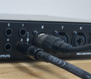
µZ measurements require a loopback of the speaker signal. To create this loopback, connect line output 2 to mic/line input 8 using the short TRS jack cable. See picture below:
Microphones
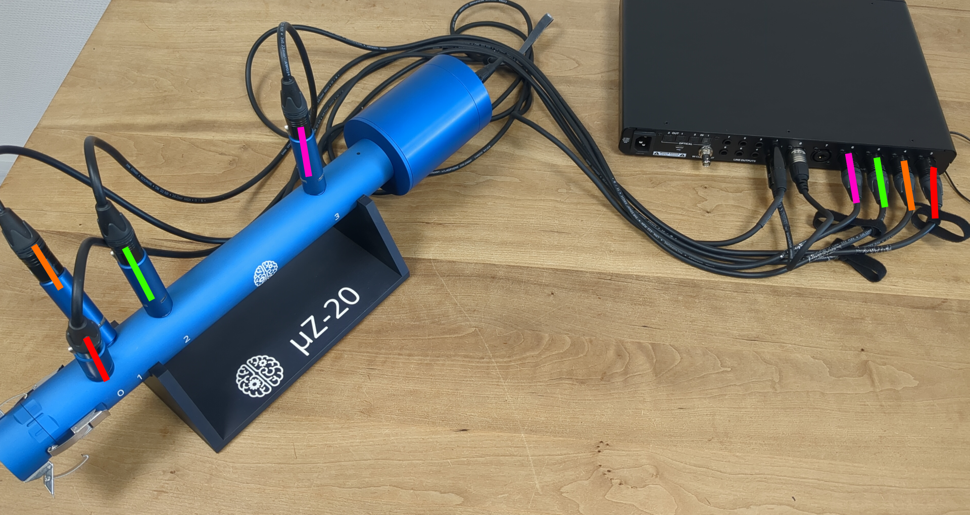
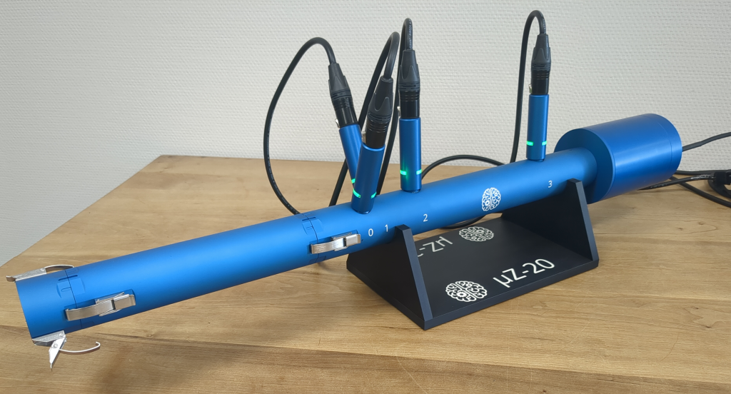
Connect the microphones to mic/line inputs 3 to 7 on the back panel of the EVO 16, using the XLR to XLR cables. The connections are listed in the table below. The microphone indices are marked on the µZ main tube and end cap with microphone.
| Microphone | EVO 16 channel | Remarks |
|---|---|---|
| 0 | 3 | |
| 1 | 4 | |
| 2 | 5 | |
| 3 | 6 | |
| T(ip microphone) | 7 | Optional |
The channel connections are shown in the picture below. The colors indicate the channel / microphone connections. The picture shows the system in 4 microphone mode. Therefore, the tip microphone (which would be connected to input channel 7 on the EVO 16) is not shown.
The microphones will receive power from the phantom power on the EVO 16. If the EVO 16 is configured correctly, the green LEDs in the microphones will light up once the EVO 16 is plugged in, as shown in the picture below. If they don't, the EVO 16 will likely have to be reconfigured
Speaker
Connect the speaker amplifier to power using the 5V AC adapter. Once the power is connected, the LED next to the barrel connector should light up.
If using an alternative adapter, make sure to use one with the following output specifications:
| Voltage | Max. Current | Connector dimensions | Connector polarity |
|---|---|---|---|
| 5 VDC | 2 A | 2.1 x 5.5 mm | Center positive |
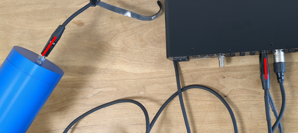
Connect the signal input socket of the speaker to the to line output 1 on the EVO 16 using the long TRS jack cable, as shown in the picture below.
