Performing a measurement
Two types of µZ measurements can be performed:
- Series impedance measurements:
Characterize samples of thin acoustic material. - Generic impedance tube measurements:
All other measurements, e.g. to determine the sound absorption coefficient of a material.
The difference between these types is that a series impedance measurement requires a reference measurement. A reference measurement is similar to the sample measurement measurement, including sample holder and disk, except that no sample is mounted. ACME uses the reference measurement to cancel out the acoustic effects of the sample holder and disk and extract the acoustic properties of the sample itself.
Before doing any µZ measurement, keep the following things in mind:
- All µZ measurements require a valid calibration, which must be performed before the actual measurements and must not be older than 12 hours.
- The calibration must at least include all microphones that are used in the measurement.
- The calibration must have been performed with the same DAQ configuration as the one that is currently active for the measurements. If this is not the case, ACME will flag the calibration as incompatible.
Setting up the software
To perform a measurement, open the Measure tab in ACME. Everything related to setting up and performing measurements can be found here.
The following section contains information about the signal generator and other measurement settings that are applicable to all µZ measurements. Information about settings that are specific to a certain type of measurement can be found in the relevant sections of this user guide.
warning
Some of the settings discussed below are critical. This will be indicated. The system might not achieve its optimal accuracy or might not work altogether, if a different value is used.
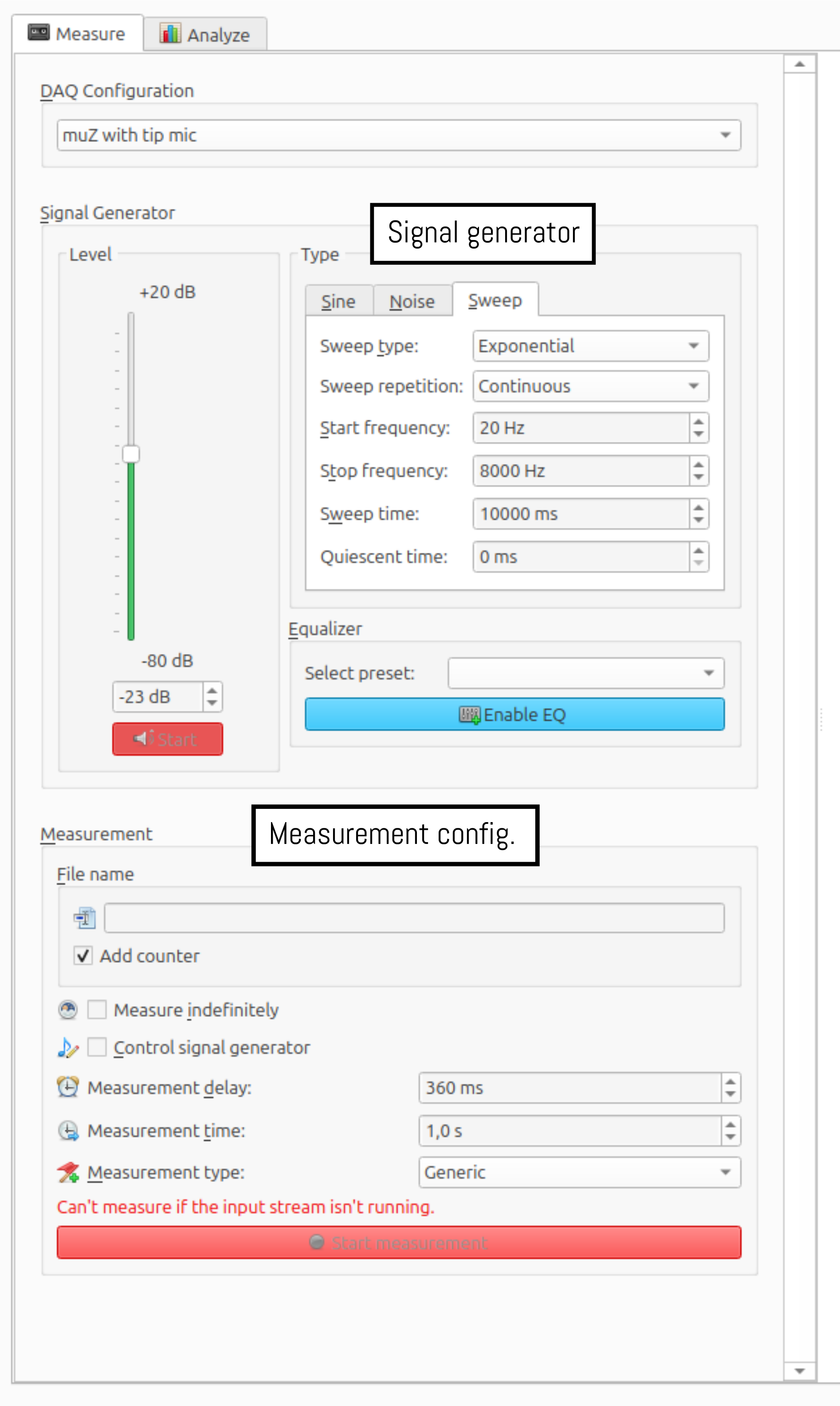
Signal generator
The signal generator settings are indicated in the screenshot above with a black rectangle. µZ measurements can be performed using either a sweep or a noise signal. The recommended settings for both signal types are described below.
note
Sweep is often the best method for µz, because it allows for a two-stage measurement. This yields a better signal-to-noise ratio. See Two-stage measurement below for details.
important
After each measurement, the software checks the channel labeling. This check relies on a sufficiently high signal-to-noise ratio. If the software indicates that the channel labels are wrong, try increasing the Measurement time to at least 20 s.
Sweep
The recommended signal generator settings for a sweep signal are shown below. More details about the meaning of each of the settings can be found at Signal generator: Sweep. The settings shown are for a µZ-20 system1.
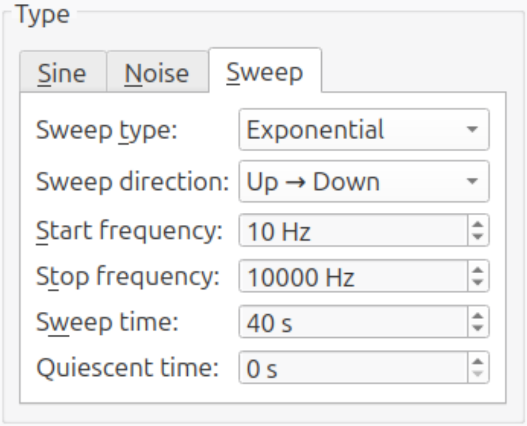
- Start frequency: This setting determines the lower limit of the measurement range. Data below this frequency will not be reliable during analysis. For optimum accuracy, set it to 1 octave below (factor 0.5) the lowest frequency in the desired analysis range.2
- Stop frequency: This setting determines the upper limit of the measurement range. Data above this frequency will not be reliable during analysis. For optimum accuracy, set it to ⅓ octave above (factor 1.25) the highest frequency in the desired analysis range.2
- Sweep time: This setting, together with the
Number of sweepsin the other measurement settings, determines the length of the measurement. Lowering the sweep time will shorten the measurement time, but will also reduce the quality of the measurement data. The absolute minimum value for this setting is 10 seconds. Below this value, the automatic equalization will fail. - Other settings: The other settings should be set as shown in the image above.
Noise
The recommended signal generator settings for a noise signal are shown below.
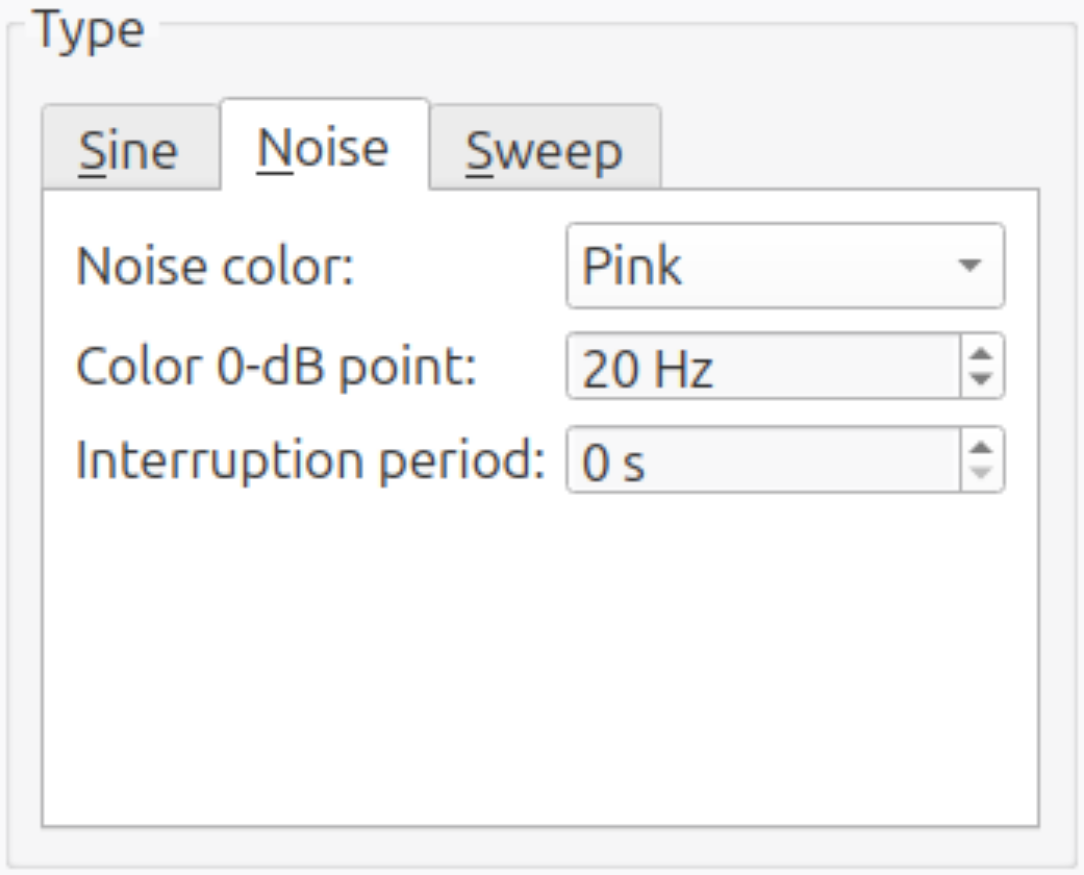
- Color 0-dB point: This changes the signal level balance between high and low frequencies. A lower value will improve the signal-to-noise ratio at the lower end of the measurement range, while a higher value results in a stronger and cleaner signal above the
Color 0-dB point. If a bandpass filter is used, there is no advantage to picking a high value and it can be left at 20 Hz. Otherwise, a sensible range for this parameter is 10 ... 200 Hz. - Other settings: The other settings should be set as shown in the image above.
Band-pass equalizer (Noise signal only)
A noise generator generates a broadband signal, containing all frequencies up to the Nyquist frequency. This excites the system at frequencies which are not of interest, as the measurement range of a µZ systems is narrower. Additionally, some samples may exhibit non-linear behavior or be sensitive to overload in certain frequency ranges and should not be excited at those frequencies.
For this reason it is recommended to band-pass the speaker signal to either the measurement range of your µZ system, or the sample under test, whichever is narrower. There is no need to expand the frequency range slightly, as is necessary for the sweep signal. In ACME, this can be achieved by applying an Equalizer to the output signal. To create an equalizer, right-click the drop-down menu labeled Select Preset and click Create new equalizer.... This will open a dialog.
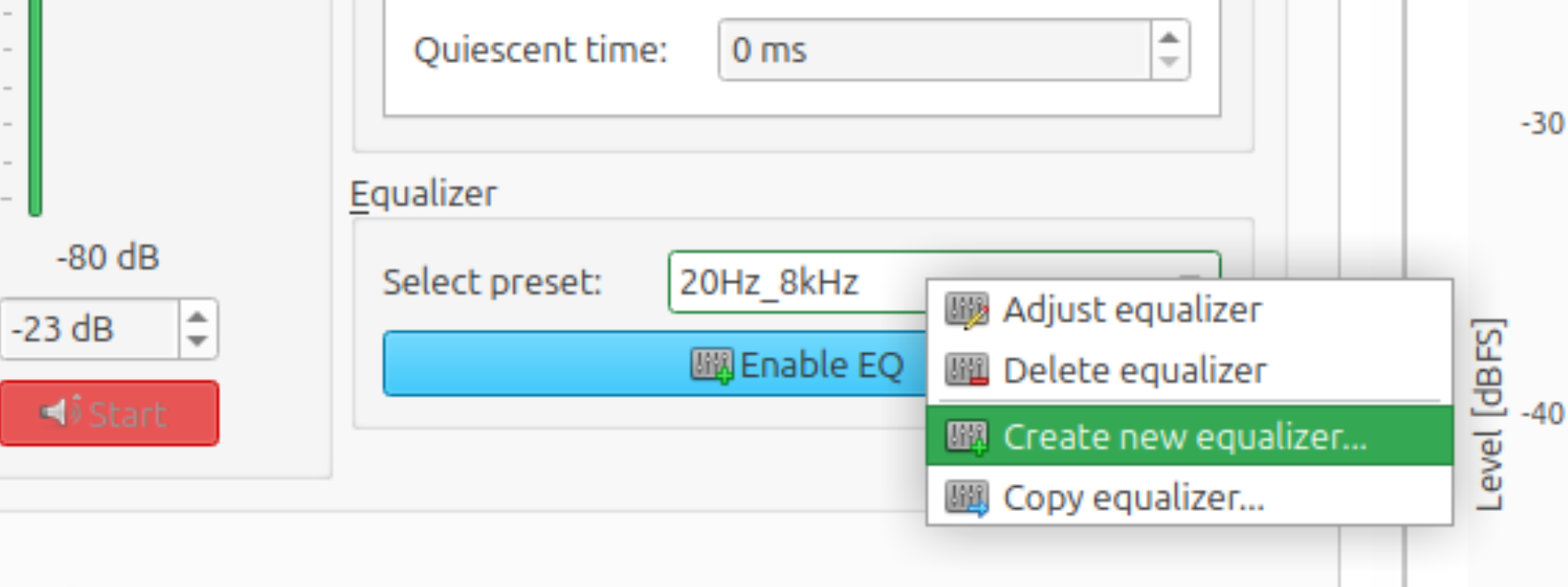
In the dialog, drag the sliders corresponding to the third-octave bands that are outside the desired measurement range fully down. Leave the other sliders unchanged. The EQ shown below is set up to use the entire measurement range of the µZ-20 (20 Hz - 8 kHz).
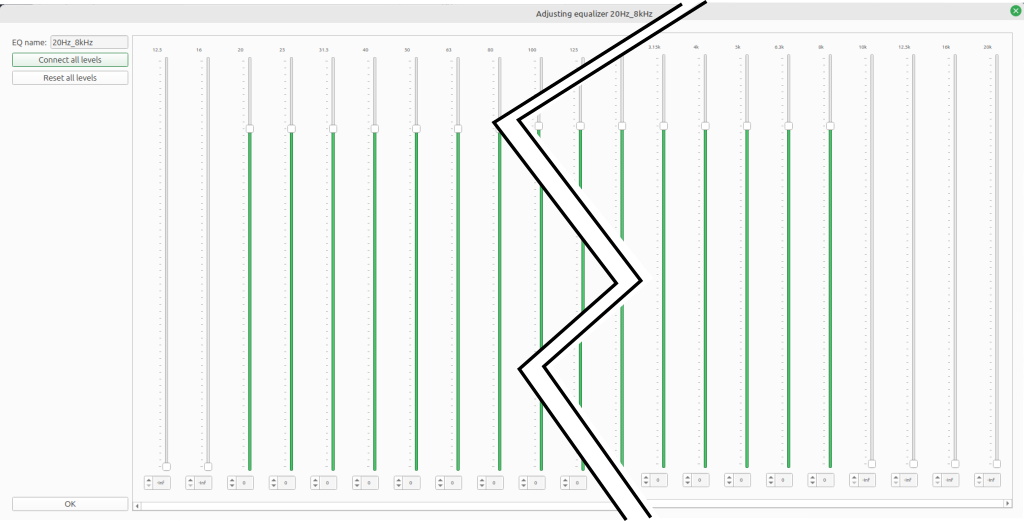
Save and close the new equalizer by clicking OK. Then enable the equalizer by clicking the Enable EQ button.
Signal level
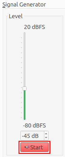
The optimal signal level takes the following factors into account:
- Maximize the signal-to-noise ratio
- Avoid overloading the microphones
- Avoid overloading the sample
- Avoid creating turbulence through the empty sample disk during the reference measurement3
When using a sweep. the speaker output level as used in the calibration wizard is often a good starting point for measurements with the 5 microphone method.
For other settings or configurations, the following procedure can be used to find the right signal level:
Quick check:
- Set up the system hardware as is will be used during the measurement, including the sample holder, empty disk and/or end cap. Leave out the parts out that will not be part of the measurement.
- Enable the signal generator by clicking the
Startbutton. See the image above. - Set the level slider such that the microphone channel with the highest level peaks at around -8 dB.4 5
tip
If a sweep signal is used, the Sweep time can be shortened to 2 seconds during
the test. Remember to return the parameter to its original setting before
starting the actual measurement.
Full check:
- Perform the quick check.
- In the Toolbar, open the
FFT settingsmenu. Use the following settings:FFT length: 8000Window type:Rectangular
- Set the signal generator to a
Sinewave with a frequency of 96 Hz6. - In the
Real Time Spectrum Viewer, open theSettingsmenu. Select the following settings:Output type:Auto powerTime weighting:Fast (0.125 s)Auto power channel: tip microphone (5 microphone method) or microphone 0 (4 microphone method)Frequency weighting:Z-weighting (unweighted)
- Unfreeze the
Real Time Spectrum Viewer. The graph shows a peak at 96 Hz and at multiples of it.- 96 Hz is the fundamental frequency.
- The multiples are harmonics and indicate harmonic distortion.
- If required, decrease the level slider until the level of each of the harmonics is at least 50 dB lower than that of the fundamental.
Other measurement settings
The general measurement settings can be found on the bottom half of the Measure tab in ACME. The The recommended settings for µZ measurements are shown below.
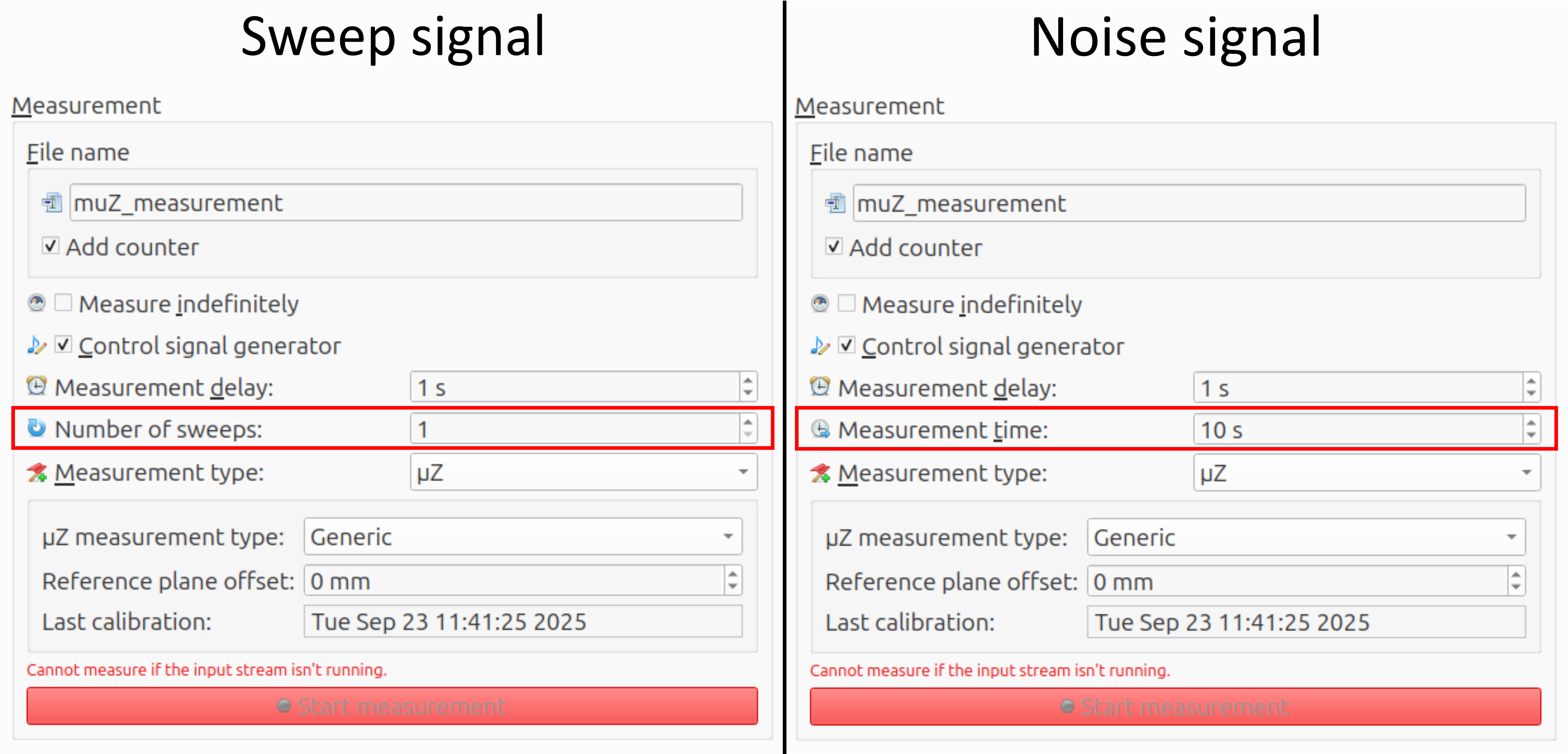
- File name: The base file name and whether to add a counter can be chosen freely by the user.
- Number of sweeps (sweep signal only): This affects the measurement time. It is recommended to use a single long/slow sweep, rather than multiple short/fast ones.
- Measurement time (noise signal only): For noise signals the measurement time can be set explicitly. The measurement quality increases with measurement time. This value should not be set below 10 second.
- Measurement type: To set up a µZ measurement, this has to be set to µZ. The options at the bottom depend on the
µZ measurement typeand will be discussed in the associated sections of this user guide. - Reference plane offset: The reference plane is the location at which the analysis will be performed. By default, it is the plane at the open end of the main tube. A positive offset shifts the plane away from the loudspeaker. A circular tube with the same inner diameter as the µZ system is assumed to be connected between the sample and µZ system. For Series impedance measurements, the offset is 0. For generic impedance tube measurements, see the explanation on the page Generic impedance tube measurements - Measurement settings.
- Other settings: The other settings should be set as shown in the image above.
Start the data streams
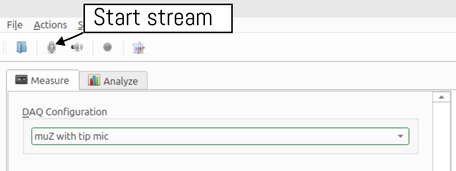
Before starting a measurement, first start the input and output streams in ACME by clicking the microphone button in the toolbar, as shown in the image below. This will start both streams, since the Audient EVO 16 is set to run in duplex mode.
Two-stage measurement
µZ measurements with a sweep signal are performed in two stages, just like during the calibration. An additional dialog shows the progress.
warning
Since these two-stage measurements will be equalized automatically, make sure no other equalizer is enabled when starting the measurement.
A sub-set of the checks that are performed during the calibration will also be performed here. The definitive measurement is saved automatically.
-
The frequency limits for the
Start frequencyandStop frequencyare linked to the frequency range of your µZ system. ↩ -
The quality of the measurement data is reduced near the edges of the frequency range. To ensure clean data across the entire frequency range of interest, the frequency range for the measurement must be extended. Note that analysis with the µZ tool will only return data within the frequency range of your µZ system, regardless of the specified measurement range. ↩ ↩2
-
This seldom is a problem. It can occur when using the 4 microphone method to measure an empty sample disk with a small hole, e.g. 2 mm. The 4 microphone method is generally not the right choice for those disks. ↩
-
The input gain on the EVO16 used to be set to 0 dB for all microphone channels. In that case, the PPM should peak at -15 dB. In October 2025, we have updated the gain to +7 dB to make the PPM reflect the input range of the microphone. Now the PPM reads levels which are 7 dB higher. See the Audient EVO 16 page for instructions on how to update the gain. ↩
-
Capacitative / compliant materials, like membranes, may resonate in the measurement range. If this is case, it is possible that the previously suggested signal levels will yield distorted results. If this occurs, try redoing the measurement with a lower signal level. ↩
-
96 Hz may seem to be an arbitrary choice, but it is not. For
RectangularFFT windows it is important that an exact integer number of periods fits inside the window, to prevent spectral leakage. It is also possible to set the FFT length to48000and use any integer frequency, but this makes the computation much heavier. ↩